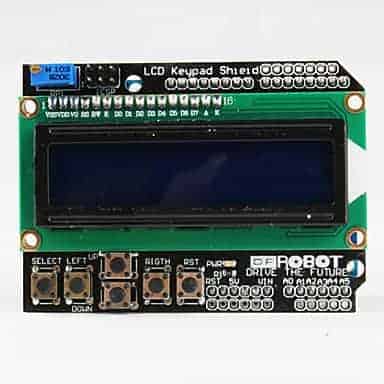

#Dfrobot lcd keypad layout serial
There are 6 connections between the serial module and the LCD Keypad shield, all of them between pins with no labels. The second pin down is SDA (data) and it goes to the Arduino A4. On the serial module, the top pin is SCL (clock) and it goes to the Arduino A5. Another option is to use the lower two pins on the I2C interface for power, but I found it more convenient to use the pins as described above. The first of these is ground, and the second of these is +5v. Holding the serial module with the I2C interface at the left hand end, there are 16 pins at the lower edge. To the right, adjacent to that are two unlabelled pins which are both ground. The LCD module has a pin on the lower side labelled "5.0V". Thanks to ChaitanyaM17 who provided the Fritzing diagram which depicts the connections, described below. This one at also identifies some of the devices found. There are several simple I2C scanners available from various sources. The address your device actually uses can be checked with an I2CScanner. Furthermore, there is a second almost identical device, the PCF8574A which has identical functionality to the PCF8574 but covers the address range from 0x38 to 0x3F. I have not tested this, but it seems almost certain that by bridging one or more of these pins to the adjacent pads, the I2C address can be controlled over the range from 20 to 27. These appear to be brought out to pads on the backpack board where they are labelled A0, A1 and A2. I was unable to find any connection to the INT pin of the PCF8574T.Īs mentioned above, the PCF8574 has 3 address control pins. However, that function is provided by a separate similar pot on the LCD shield, so this pot on the serial module has no function. When connected directly to the LCD, this pot will control the contrast of the LCD. In addition this module has a 10K potentiometer connected between +5 and Ground, whose variable lead is brought out to pin 3 (third from the bottom in the photo). With 0.1 mA of base current, it should be able to maintain a LOW condition at its collector (module Pin 16) with at least 20mA collector current. The label on the transistor says L6 which according to my research probably makes it a MMBC1623L6 which has a minimum current gain of 200. That is, the LCD backlight is turned ON when the P3 pin is Low, and OFF when the P3 pin is High.
#Dfrobot lcd keypad layout software
Because of the transistor, the logic state is reversed relative to that assumed in the software library. The emitter of that transistor is connected to Vss (ground) and the collector is connected to header pin 16, where it can be used to control the LCD backlight. In the case of P3, it is connected to the base of a transistor (visible in the photo at the top right area just under the label "LED"). On this module, all of the digital I/O pins, except for P3, are simply brought out to header pins (on the right in the photo). In the High state, it has a transient active pull-up and then a continuing pull-up current of about 0.1 mA. According to the data sheet of the PCF8574T, each I/O pin has a FET to pull it to ground for the LOW state, and can sink at least 20ma. This module is based on the IC PCF8574T which terminates the I2C protocol, has 3 pins for address control (20 to 27) and has 8 digital input/output pins P0 to P7.

By studying the labels on the LCD, I was able to identify the functions of the pins on the serial module. The serial module has the usual 4-pin header for I2C, and a set of unlabelled header pins which I understand are intended to plug directly into the underside of the LCD module.


 0 kommentar(er)
